Distortion-aware depth fade

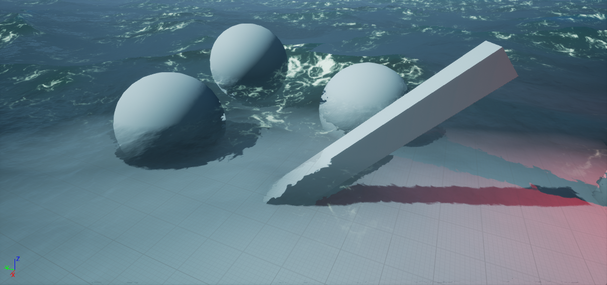
When rendering translucent surface, using Depth Fade(Difference between surface pixel depth and depth of the scene pixel behind it) to control opacity is a common way of simulation transmission of light through translucent body. It is frequently used for water rendering.

Unfortunately, when Depth Fade is used together with Screen-Space Distortion(also known as refraction), it generates visual artifacts:

https://image.prntscr.com/image/vvC0b0IlQoKe0bYEBjtKTA.png

Artifacts are caused by the fact that depth fade is calculated without taking distortion into account, and you are seeing both distorted(marked with green) and undistorted(marked with red) surfaces:

https://image.prntscr.com/image/TiZmKCPYS2qzGMT9Us-D0Q.png

I think that nobody would dare to argue, that the artifacts, visible in the picture, are not okay to live with.

There are several workarounds for the issue(for water in particular). One of them would be leaving water opacity on a quite low value and calculating fog for every pixel underwater, accounting for distance, the light has traveled underwater. Applicable to UE4, that would require you to calculate underwater fog in additional post process step, that has to be done before translucency. It would be quite hungry too, since you would need to calculate water intersection with view vector for each pixel. Additionally, you would need to duplicate the calculations in all translucent materials, that would be rendered after mentioned post process pass.

Instead of that I suggest adjusting the way, depth fade is calculated.
We need to match scene depth, that is used to calculate depth fade with distorted scene depth.
Distortion in UE4 is calculated by accumulating distortion from every refractive object and we do not have access to results of this calculation that early in the pipeline.

But we can duplicate distortion calculation of a single object in material in exactly the same way, as it is calculated in distortion pass. That should bring us to a point of virtually no visual complications, in case when water surface is the only refractive object with depth fade in the scene. It may sound restrictive, but the cases, when you would have two highly dynamic, refractive surfaces with overlaid ontop of each other, are quite rare. Even if not, in most cases the visual impact is acceptable.

Anyway, the core idea is:

  1. In translucent surface material, calculate distortion offsets, the same way, as they would have been calculated in distortion pass
  2. Sample scene depth using screen coordinates plus distortion offset.
  3. Perform depth fade using distorted coordinates.

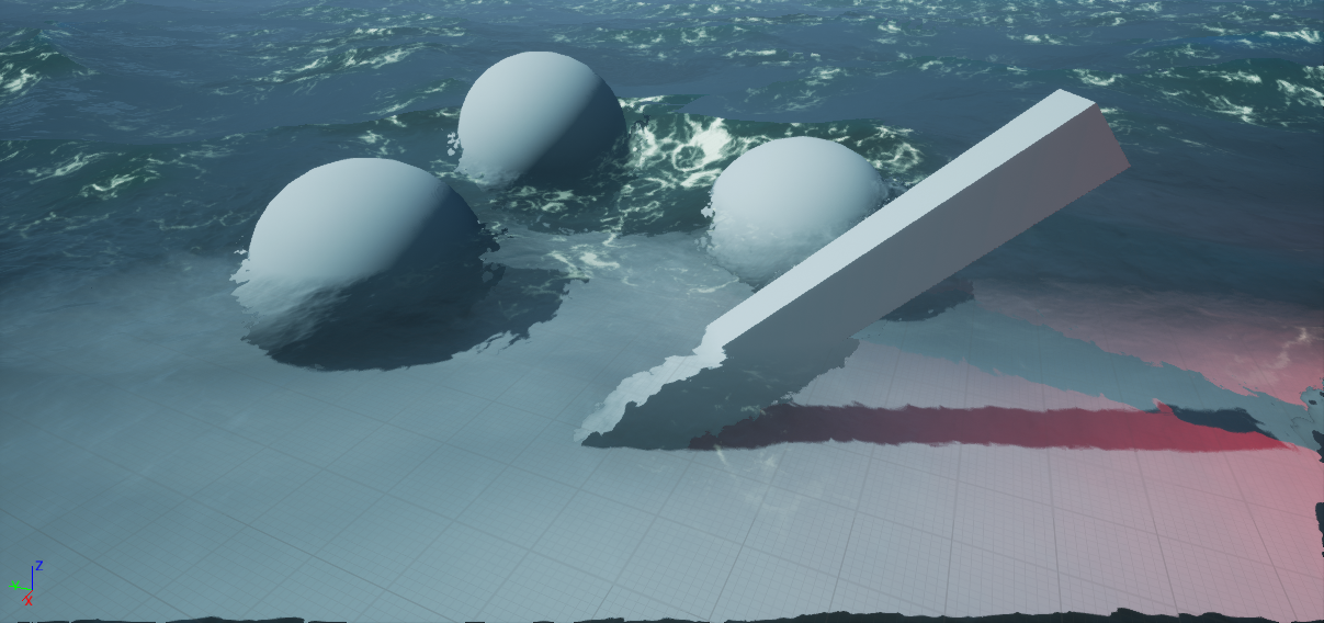
After doing so, this is what we should get:

https://image.prntscr.com/image/s5djkOufT7SAmCqqzwmUWQ.png

And here is an example how to implement it:

You can grab custom node code here. (Must have a linked github account.)

Just copy/paste the whole file contents into a custom material expression.

Custom node inputs:

  • Refraction - Plug in the same node network, as in Refraction material input pin.
  • Normal - Plug in the same node network, as in Normal material input pin.
  • Opacity - Same as Opacity input on Depth Fade material function.
  • DepthFadeDistance - Same as FadeDistance on Depth Fade material function.

Custom node outputs:

  • R - Distorted Screen Space coordinates, x
  • G - Distorted Screen Space coordinates, y
  • B - Distorted Scene Depth
  • A - Distortion-Aware depth fade(same as Depth Fade material function output

Example Material Graph:

https://image.prntscr.com/image/w5tQ_TegShuPRZqMvmnCFg.png

In the custom node code there is a USE_MIRRORED_WRAP_EDGES define that you can change, to toggle edge mirroring code kindly provided by Kalle_H. It is enabled by default.

Old irrelevant WIP post under the spoiler:
[SPOILER]
I’ve ran into a bit of a complication with screen-space distortion(aka refraction), when used together with depth fade.

https://image.prntscr.com/image/31_pY29MTGqdOZCVTf89Dw.png

Well that is pretty much expected and common sense tells me that I should switch to depth fading using distorted scene depth.

My problem is that I can’t match distortion, even if the math looks to be exactly the same as in distortion shader.

This is the closest I could get:

https://image.prntscr.com/image/TOplEoUQShaW86Bq2Nci5Q.png

It is lousily close, and distorted depth fade seems to roughly follow distortion, but it is not anywhere near perfect match I’d expect and I am somewhat lost in searching for a cause of discrepancy.

I would appreciate any assistance.
[/SPOILER]

Would love there to be a fix for this as well. Can’t we just apply the distortion effect in a pass after the base color and before the lighting?

just curious, as Refraction Mode are you using Index of Refraction or Pixel Normal Offset?

Handling both.

you mean you tried both? you can’t use both at the same time :smiley:
I’d expect you’d need to use the PixelNormalOffset mode for it to work. might help to see your math

Not doing both at same time, just handling both cases.

The math is copied exactly from DistortionAccumulatePixelShader.usf and used to get distorted coordinates. Those are then used to sample scene depth and calculate depth fade for opacity based off distorted scene depth in water material shader,

Easiest way is to get it working is to use SceneColor instead of refraction. Then you can also calculate correct transmission based actual optical depth.
Refraction is based on accumulated offset values so you can’t calculate correct offset when there is overlapping refraction elements.

Cheers for the answer. Yep, I’m aware that distorting scene color in water material would be a far less problematic and more favorable approach overall, but for the particular job it is out of question.
I will deal with distortion accumulation a bit later(or won’t be dealing at all). For now I’d like to get it operational with distortion coming from water alone.

Then I need to see your code how you calculate distortion.

Have you accounted magic scale value that is applied at https://github.com/EpicGames/UnrealEngine/blob/master/Engine/Shaders/Private/DistortApplyScreenPS.usf


static const half InvDistortionScaleBias = 1 / 4.0f;
DistBufferUVOffset *= InvDistortionScaleBias;

Nope. I’m skipping multiplication by 4 and division by 4 completely, as well as another two lines of code, where offsets are separated into positive and negative, as there is no buffer involved between obtaining offsets and using them.

I’ve narrowed down the problem a little.
It seems like the code itself is fine, for when I disable displacement and WPO, depth fade comes to a perfect match as expected:

https://image.prntscr.com/image/jURhR4eLRJCteHs7Ya13Ng.png

When either WPO or Displacement is used, there is a discrepancy:

https://image.prntscr.com/image/9HNCYlAmS3mR0tPK0ot39g.png

Custom node has 4 inputs:
DistortionParams(InvHalfTanFov,view width to height ratio, view width and height).
Refraction(same, that is connected to material refraction slot)
ViewNormal(Final material normals, transformed to view space)
ViewVertexNormal(mesh vertex normal, transformed to view space)

RefractionParams and Refraction are definitely same, with or without displacement.

So I believe the error most be somewhere here:

https://image.prntscr.com/image/LjrIeEcCT6SUwuJB7XHPpg.png

I think ViewVertexNormal is different in distortion accumulate pass(WPO/displacement is accounted for?)

What is “TO Material normal input”? Try to normalize after you transform from tangent to view and not before. Is vertex normal recalculated in tesselation stage?

TO Material normal input connects to material Normal pin.
Changing location of where normalization is placed does not have any effect.
Vertex normal is not recalculated in tessellation stage.

To even further simplify things, I have disabled tangent space normals on material.
The normal I am now using for material normal pin and distortion custom node is set to a constant :


normalize( float3(0,0.5,1) );

In the custom node


ViewNormal = normalize(TransformWorldVectorToView(Normal));
 

World to view transform should not depend on anything tess or WPO related.
Then:


ViewVertexNormal = TransformWorldVectorToView(float3(0, 0, 1));

Working from assumption that vertex normal is always pointing up, disregarding displacement.

In this case, I would expected distorted image to be uniformly shifted in some direction, disregarding if WPO or displacement is used and a perfect match with distortion and depth fade.
And that is correct:

https://image.prntscr.com/image/6hDOkXGST_SWRRfeffAcyw.png

Now I replace constant normal


normalize( float3(0,0.5,1) );

, with a complex node network, that calcualtes normal


normalize( ToMaterialNormal);

In this case I would expected refraction to have varying distortion and a perfect match between distortion and depth fade.

Well, it is not matching:

https://image.prntscr.com/image/P3BanFjaQ8mWD3hEfuCrQg.png

Why the hell? I have absolutely no clue. There are no transforms involved. There is virtually nothing, that should affect it. The network contains NormalFromHeightmap, And two BlendAngleCorrectedNormals with two texture samples and lerp based on foam

At this point I’m starting to suspect that… the issue must be in my node network, that calculates the normal, mustn’t it?

I’m cross checking it by substituting node network for normal calculation with just one texture lookup:

And:

https://image.prntscr.com/image/xnZuyEf9S6y5XZdNPDZg6A.png

https://image.prntscr.com/image/qmaLE4J7S2qoGWnhahhJlQ.png

Surprisingly it works as expected.

So far, the conclusion should be, that something is being calculated differently with and without WPO/Displacement for my normal calculation network, while the distortion calculation itself is fine.

Tracked down the issue to one Absolute World Position node in normal material network, that was using position with material offsets excluded. Shame that it consumed that much effort, especially considering that the problem was not in distortion calculation all along :frowning:
Huge thanks to everyone who responded.

Still gotta fix screen edges and add minor tweaks like better biasing.
As Kalle-H mentioned, this approach would give problems, when there are two refractive surfaces stacked together on screen, but overall, seems feasible.

Really nice. Might be using this technique myself on some materials too. I have fixed screen edges by using mirrored wrap. Just clamping or wrapping at edges give really bad look.


    float2 DistortScreenUV = ScreenUV + Distortion;

    // Apply mirror distortion if DistortScreenUV is outside of borders.
    half2 ScreenEdgesMin = half2(-1.0, 1.0) * ResolvedView.ScreenPositionScaleBias.xy + ResolvedView.ScreenPositionScaleBias.wz;
    half2 ScreenEdgesMax = half2(1.0, -1.0) * ResolvedView.ScreenPositionScaleBias.xy + ResolvedView.ScreenPositionScaleBias.wz;
    if (DistortScreenUV.x < ScreenEdgesMin.x || DistortScreenUV.x > ScreenEdgesMax.x)
        Distortion.x = -Distortion.x;
    if (DistortScreenUV.y < ScreenEdgesMin.y || DistortScreenUV.y > ScreenEdgesMax.y)
        Distortion.y = -Distortion.y;
    DistortScreenUV = ScreenUV + Distortion;


Does all this require manually editing the individual material shaders? Isn’t there a universal fix to this problem that works well, like editing the behavior of distortion or pixel depth when used on a material with refraction? I’m still not quite sure on the steps needed to fix this issue.

Refraction is done as post process. Depth fade is done per material. Basically there is no perfect solution for general case.

I guess to solve depth fade for a general case, one would need to make distortion pre-pass. Definitely not worth it I think. I’m unaware about issued with pixel depth when used on refractive material. PDO is not taken into account for distortion I’d guess ?

Updated first post in the thread with code and example how to implement what was discussed here through material custom node.

thanks for the detailed update!
subscribing to keep it for future reference :slight_smile: