Actually realistic water shader

I’ve searched and searched but I cannot find a tutorial for implementing a realistic shader for the scattering of water in light.
I want to know how to implement realistic light attenuation or know if it can’t be done.

For reference light travels in water like this:


The player also has a flashlight so it would be nice to get it working with non-static lights as well.

Single layer water shading model already approximates that for you.

I can’t find anything on how to use the “single-layer water shading model”

Same. Seems like there is still no documentation.

… so, just to nitpic. Can’t we get the mathematical formula instead of the graph?
you need something that checks mixed channels if you follow the graph to the letter, so it does not seem like something possible without Custom nodes or a Custom shader (like single layer water).

Second.
Scattering of light in water = water caustics?

Third.
“implement realistic light attenuation” + “flashlight” ?
does this mean underwater or looking into water with a flashlight?
2 completely diffetent situations here.

From underwater a post-process with decent values can fake the effect.

From above, shining a light into water usually makes you see even less, really depends on the clarity of the water i suppose.
Either way its not exactly a simple scenario to mimic.
The pixel shader can offset those values, but it isn’t something cheap to do…
Also, it goes all back to ray marching…

Ryan Brucks has a slide about this material from his Unrealfest presentation. You can still register and watch the videos on demand: Unreal Fest Online 2020 - Unreal Engine

It should be pretty self-explanatory.

Opacity input controls how much subsurface you are seeing. At zero, you see both surface plus subsurface. At 1, you observe only surface. Can be used for something floating on the water, which is not water :). Foam, leaves, whatever.

Refraction input is already described in documentation for other translucent materials.

Additionally, single layer water material output has 3 pins:

Scattering Coefficients
Absorption Coefficients.

These are 3 channel vector values, that control how much red, green and blue light is absorbed and scattered. They should be pretty low.
Scattering phase. -1 to 1. Controls directionality of scattering.

Basic clear water material has roughly following values:

BaseColor -(0, 0, 0)
Specular- 0.25
Roughness- from 0 to 1
Refraction - 0.75
Metallic - 0
Normal - Normal map as per flavor.

Scattering Coefficients (0.0007, 0.0021, 0.0025) * 0.01
Absorption Coefficients (0.35, 0.07, 0.03) * 0.01
Scattering Phase 0.1

Have fun.

2 Likes

Thanks; I couldn’t find anything on what would be appropriate values for those 3 special fields.

Is there a way to add Depth Fade to the Single Layer Water shader?

Pic from the talk.
it also shows other layers being added in as he covers what they do.

As you can see, because managing small values is hard, they just use 1/ node to get them in range.

No, but there is already a depth fade hardcoded in the shader. You can edit that one.

here’s a good question…
​​how do you do that without actually modifying every other project?

Meaning, can the .usf be somehow inherited or instanced like we used to do for something like the skysphere BP?

This is really helpful! I was personally trying different values and had a lot of trouble getting the water to look any bit realistic.

I haven’t gotten a chance to look through the slides to see what they used for inputs on their example, unless it was just the one slide.

I also asked on the atream and I believe Ryan Brucks said that they plan on releasing some examples with the new water system in 4.25, so when those come out it should help as well.

Seems like a skydome is required if you’re going to be viewing the water from underwater looking out. SkyAtmosphere actor just turns black without a dome for me.

Yeah, that is because they are physically based and values do not change intuitively(different scale for scattering and absorbtion).
But in the same instant, it means that you can pull values from a research, where optical properties were measured somewhere on the planet, plug it in, and it will work reasonably good.

Parameters can vary significantly from what kind of water are you trying to depict.

This, is very exciting. I read this while looking for a water solution. The water types the opactity and depth settings, obviously are forcing some reading.

As 1.33’ is generally the agreed refraction value of clear water. I applied this to my material. The results looked satisfactory. I considered snells law and decided, decided to replace my surface of water with a solid volume, because I considered variation in the under currents would have an effect on the angle of incidence. I had a homer moment when I realised materials can only be placed on surfaces and that it is the material that needs the depth. Hence now needing to go and read all about the material models, because I cant buy one on the market place… Hint !!!

For anyones interest here is the effect of refraction upon a translucent surface.

So I know this thread is a bit old, but if you’re having problems with water refractions, make sure to use the correct physical IOR and set Pixel Normal Offsets

pixel_normal_offsets.png

In addition, for the curious, I grabbed these input values from the stream mentioned earlier and they provide a pretty good base for stylized water

One problem is, that the posted graph is about light attenuation, aka how much % from your incoming light of each frequency you will still be able to see a a certain depth (there is a light attenuation coefficient and some higher math at google ^.^), while the mentioned scattering/caustics is caused by refraction and depends on the index of refraction for each wavelenght.

Biggest problem i see so far: Those calculations could be implemented, and calculated for certain wavelenghts, f.e. for those 7 colors/wavelenghtsfrom the graph. However, UE and almost every engine don´t use wavelenghts, we use RGB colors or variants of it. So while every light from the graph would be an independent wavelenght, like red 650nm, green 550 nm, blue 450nm, or violet ~425nm 8range is given from 380 to 450nm), in RGB most colors are just a mix of the RGB colors. F.E. yellow is red 255, green 255, blue 0. while it has it´s very own wavelenght, which is independent from red and greens wavelengths.
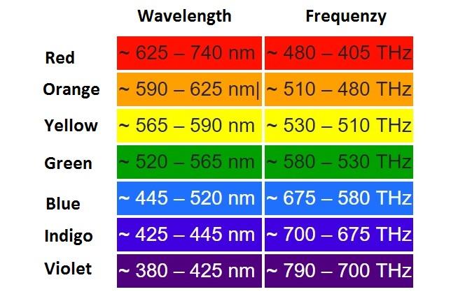
So in theory, you would need to convert and split your light calculation into those wavelenghts (minimum 3 for RGB), then do your absorption and refraction stuff, then convert the results back into RGB colors, that the comp can display.

Well, maybe it isn´t that complicated, if you set up some filters in post process, which filter out red, green and blue according to your graph for certain depths, with red being reduced to zero at a few meters, while blue and violet travel really deep.
Since your flashlight would start from where the player is, and not from the surface, it would probably be easier to split it into 3 lights, one for each main color, and set it up, that red have the shortest range, and blue the longest.